
APPLICATIONS
Use pressure forming when the part will be the “face” of the product expecting a long life. We can pressure form a company logo or model designation with styling lines, surface texture or other features in a light weight and durable part. Use pressure forming when there are undercuts or rims and a greater depth of draw.
CAPABILITIES
Pressure forming competes with injection molding in terms of surface detail where sharpness and crispness of styling lines and logos is important. It has much more affordable tooling with a shorter time-to-market with easier updates and modifications.
HOW IT WORKS
Pressure forming uses both vacuum and air pressure to push the soft, heated plastic more tightly against the mold giving the part sharp detail.
Pressure forming produces parts that have crisper detail and sharper features than conventional vacuum formed parts. In fact, pressure forming rivals injection molding in its ability to produce highly detailed features and surface cosmetics.
Styling Features: Logos, model designations, and other text and images can be pressure formed into the surface with details as sharp as a plastic injection molded part.
Defined Edge and Corner Radii: Parts with sharp corners—parts that cannot be made by conventional vacuum forming—can be produced using the advanced capabilities of pressure forming.
Significant Depth of Draw: Three-dimensional parts that have a significant third dimension (or depth of draw) can be produced through pressure forming.
Undercuts: Parts with inverted return lips or recessed features on sidewalls are excellent applications for the unique capabilities of pressure forming.
Less Expensive Tooling Than Plastic Injection Molded Parts: Tooling for a pressure-forming part can be as much as 90% cheaper than tooling for a plastic injection molded part!
Quicker to Market than Plastic Injection Molded Parts: Because the tooling for pressure-formed parts is much simpler than tooling for injection molded parts, pressure-formed parts can be into production much faster than injection molded parts, and that gets the finished product to market that much quicker.
Product Redesigns and Updates Are Easier: If a plastic injection molded part needs to be modified—because the product of which it is a critical part undergoes a redesign, improvement, enhancement or facelift—a significant investment in new tooling is required. When a pressure-formed part needs to be modified, the existing tooling can often be modified quickly and affordably to implement the change.
Flexibility to Offer Variations of a Base Design: The tooling used in pressure forming can be quickly and economically modified to create parts or panels for different configurations of a basic product or different models within a product line. Replaceable inserts within the mold enable changes to be made in styling features, model designation, logo, ports or openings in the pressure-formed part.
Parts, panels, enclosures and other components that need to have crisp detail, sharp corners and precise surface cosmetics on one side are ideal applications for pressure forming.
Bezels and Fronts: The housing of a CRT, touch screen or liquid crystal, flat panel or plasma display is an excellent candidate for pressure forming. A logo, company identification, model designation, surface texture and styling features can all be included in the design to produce a bezel that is attractive, durable and very affordable!
Exterior Panels: An instrument or control panel that requires precise openings for gauges and controls, but also needs to be attractive and rugged, can be produced very economically using pressure forming.
Three-Dimensional Housings and Enclosures: The exteriors of business machines, office equipment, medical and diagnostic equipment, electrical and electronic devices, and other consumer and commercial products that have large depth of draw are excellent applications for pressure forming.
Doors, Hatches, Covers and Movable Panels: Panels that face the user, and need to be durable and have crisp surface detail, are prime candidates for pressure forming. They can be affordably produced with an attractive exterior finish, and indentations and cutouts for hinges, latches, handles, brackets and other hardware will be precise and consistent.
Panels with Undercuts and Returns: Parts with edges that turn inward or under, or panels with sections that wrap back on themselves, cannot be produced through conventional vacuum forming, but can affordably and efficiently be pressure formed.
Wide Range of Resins, Colors and Finishes: There is no limit to the combination of base materials, colors, exterior details and finishes that can be incorporated into a pressure-formed part. The part can be produced with an inherent color in the resin, so no painting is required, or the pressure-formed part can be painted and/or screen printed, and the surface can be hot stamped or given other finishes.
EMI/RFI Shielding: For electrical or electronic equipment that require housings with EMI and/or RH shielding, pressure forming is again an affordable option. Shielding can be applied to required specifications in a secondary operation.
Thermal, Acoustic and Other Insulation: While the exterior side of a pressure-formed part is highly detailed and precise, almost anything can be attached to the backside of the part, such as thermal or acoustic insulation.
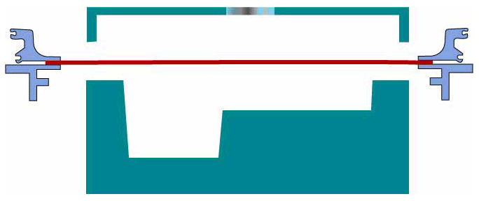
Pressure forming is similar to conventional vacuum forming in that thermoplastic material is formed against a contoured surface using a vacuum to draw the material against the mold, with normal atmospheric pushing against the backside of the material. Through modification of the tooling and forming equipment, pressure forming uses a vacuum to draw the thermoformed material against the surface of the mold, but also applies significant positive air pressure to the backside of the part being formed. This produces a dramatic increase in the pressure applied against the surface area of the mold.
Increased Air Pressure: In a typical thermoforming or vacuum forming application, readings of 20 inches of vacuum (9.8 psi) to 25 inches of vacuum (12.25 psi) are the norm. Average readings run about 22 inches and, in unusual cases, vacuum pressure can go as high as 28 inches. Depending upon the size of the mold and its design, positive air pressure against the back of the thermoformed sheet can be increased nearly tenfold, pushing the heated sheet of plastic tightly against the surface of the mold.
Increased Surface Detail: This allows for surface features so sharp they rival injection molding in their detail. This also enables the plastic to pick up grained surface details, develop tight radii for styling, and attain smoother surface finishes. The differences between conventional vacuum forming and pressure forming are shown in Figures 3A and 38, 4A and 4B, and 5A and 58. The images on the left represent the results with conventional vacuum forming, while the images on the right show the benefits of pressure forming.
Pressure forming uses both a vacuum to draw the thermoformed sheet into the cavity of the mold, and positive air pressure to push the thermoformed sheet tightly against the surface of the mold, picking up precise surface details.
Pressure Forming and Injection Molding Comparison
| Pressure Forming | Injection Molding | |
|---|---|---|
| Tooling Investment | Up to 90% less than tooling for injection molding! | Five to ten times more expensive than tooling for pressure forming |
| Re-Tooling Investment | Also up to 9096 less than cost of injection molding re-tooling | Also five to ten times more expensive than tooling for pressure forming |
| Time to Market | Tooling can be developed in just six to ten weeks | Development of tooling can run three to six months, or more |
| Part Characteristics | Sharp, crisp details and features, but on just one side | Sharp, crisp features on both sides |
| Durability of Part | Equal to injection molded part | Equal to pressure-formed part |
| Available Resins | Wide selection to choose from | Wide selection to chose from |
| Adaptability of Tooling | Fooling can affordably and relatively quickly be modified | Entire tooling has to be re-designed and built anew |
Resins that are classified as thermoplastic can be used in vacuum forming and pressure forming. Theoretically, all thermoplastics can be thermoformed, but it is not always practical because special equipment and forming techniques are required.
Resins to Consider: These are the more common materials used in thermoforming.
HIPS (High-Impact Polystyrene)
ASA (Acrylic Styrene Acrylonitrite)
ABS (Acronitrile-Butadiene-Styrene) and ABS blends
Acrylic
PC (Polycarbonate)
HDPE (High-Density Polyethylene)
HIVEWPE (High Molecular Weight Polyethylene)
TPO (Thermoplastic Poly-Olefin)
PVC Alloys (Flame Rated Polyvinyl Chloride)
Conductive Plastics
PETG (Polyester Terephthalate Glycol)
Thickness: These materials can be obtained in sheet form as thin as .001-inch in some materials, or as thick as .600-inch on other materials. Most standard-sized parts produced on single stage or rotary pressure forming machines use plastic stock in the range of .062 to .375-inch gauge.
Selecting a Resin: Each plastic resin has physical characterizes that make it suitable for specific applications. Universalhas worked with nearly every type of plastic, so the Universalengineering staff can recommend a specific base material based on several factors.
Painted or Unfinished: Will the part be painted or used unfinished? How important is the finish and appearance of the part? Newer resins have just come to market that have very attractive finishes in a range of colors that do not require painting!
Durability: Will the part need to withstand a harsh environment? Will it be exposed to heat, humidity, chemicals, solvents or detergents?
Post-Thermoforming Activities: Will the part need to be screen printed or hot stamped? Will hardware or secondary components be attached to the part? Will the part need EMI/RFI shielding?
Location: Will the part be used internally or as part of the exterior of the product?
Rigidity: Should the finished part be stiff and rigid, or is some flexibility desirable?
Understanding vacuum forming requires addressing two related issues—draw ratios (sometimes referred to as stretch ratios) and material distribution.
What Is a Draw Ratio?
Whenever a flat sheet is drawn over a contoured surface, the material is going to stretch. A contoured part has a surface area greater than that of a flat sheet of the same length and width. This difference in surface area is known as the “draw ratio”. There are a number of formulae to express the draw ratios of different shaped objects, and the mathematical formulations for each of these are available from a number of sources.
Here are the three most common shapes.
Part Dimension
Box or Rectangle: D = I + where Nominal draw ratio = Height of box or rectangle
Length of box or rectangle W = Width of box or rectangle
Therefore, a formed box with the dimensions 6″ height by 10″ length by 10″ width would have a draw ratio of
2 (6) (10+10) _ 240
D = ‘1 + 1+ =3.4
(10×1 0) 100
Hemisphere: D = 2 Tr R 2
Where: D = Nominal draw ratio R = Radius of the cylinder
TrR 2+TrDH
Cylinder: D
Tr R2
Where: D= Nominal Draw ratio R= Radius of the cylinder or D= Diameter of the cylinder H= Height of the cylinder
Grain Pattern: Only grain patterns that have connecting channels between peaks should be selected as this allows air trapped in between the sheet and the mold to escape through vacuum holes, enhancing the detail of the surface. There are a myriad of grain textures available, and Kink can provide samples of each. Avoid quick fixes such as “shot peening” for this process.
Vacuum Holes: The positioning, size and number of vacuum holes are important, too. On flat areas, they should not exceed the size of any pattern mark in the texture. The more vacuum holes the better, because they will evacuate air from the mold quickly, and there will be less of a tendency to show shiny areas on flat surfaces of the part.
Styling Lines: Additional cosmetic considerations include using styling lines to add detail and depth to the part. As long as they do not create lock situations during molding, they can be used to aesthetically improve and increase the rigidity of the part, but there may be some draft and design guidelines to consider. On inverted styling lines, the distance between depressions should be at least twice the distance of the starting thickness of the forming sheet (Figures 6 and 7). The depth or height of the slots should not create secondary draw ratios that excessively thin the material, Generally, a secondary draw should never exceed a .3-to- I depth-to-draw ration. These parameters also hold true for molded-in slots, which are aesthetically superior to routed slots.
Sharp Detail and Radii: The thicker the material formed into a radius corner, the larger the radius corner will have to be. If the finished gauge of a right angle is .150″, the radius should be a minimum of around .500-inch. If the finished gauge is .050″, the radius should be approximately .020inch. This is roughly a straight-line function, but at some point in the draw ratio—when the material thins to about .015-inch very close to the right angle—the material will simply become too weak to pull through.
The radii of corners and draft angles is a key consideration in pressure forming.
Tight angles should be avoided, as they can create weak areas where the finished part may crack. On female cavities, however, the radii should vary with depth.
2-Inch Depth: Approximate radii = .030″ minimum
6-Inch Depth: Approximate radii = ,075″ minimum
12-Inch Depth: Approximate radii = .150″ minimum
Other Values May Be Interpolated
Variations in Part Thickness: This occurs for many of the reasons just given. Variations in thickness are most often caused by multiple or secondary draw ratios within the part (Figure 9). It may be necessary to design around theses problems, but if forming techniques alone do not solve them, secondary assembly measures may be necessary. To accommodate load-bearing requirements or stiffening needs, it is possible to bond spacer blocks, fastening bosses with inserts, or reinforcing blocks to the backside of the part. However, because the backside wall will probably not be uniform (Figure 10), tolerances based on individual parts must be established. Design some latitude into the part, and discuss with Universal Plastics’ engineering staff if gluing secondary pieces to the backside of the part is practical and makes sense.
Material: In determining the best material for the application, there are two major considerations.
Will It Provide the Physical Characteristics Needed in the End Product? After it’s been pressure formed, what appearance, texture, rigidity and color will the plastic have?
Can It Be Pressure Formed? How will pressure forming change any of the material’s characteristics?
Required Characteristics: These include impact strength, resistance to chemicals and solvents, paintability, weatherabilitv, stability, heat deflection, creep and stiffness. The material must also provide hot strength and flow characteristics to create a structurally functional part that is cosmetically appealing and able to accept detail.
Interim Tooling: To provide prototype parts, it may be feasible to use wood, fiberglass or non-water-cooled epoxy molds. The result attained will in no way cosmetically resemble the finished product, but it can be used to test the design and help develop the forming techniques required. Also, it is relatively easy—and not too expensive—to modify a wood, fiberglass or epoxy mold.
The single most important factor in producing a quality pressure-formed part is the tooling used to form the part!
Aluminum Tooling: To make consistent, cosmetically appealing parts, there is no substitute for machined temperature-controlled or cast aluminum water-cooled tooling. They both provide good temperature control, and they both produce parts with minimal warpage, and aluminum tooling-produced parts are dimensionally more consistent and stable.
Cast Aluminum: This alternative can be less expensive than fabricated molds. However, vacuum holes must be used liberally throughout the mold to evacuate air during thermoforming, and the tendency towards porosity limits the texture choices.
Machined Aluminum: A temperature-controlled mold machined from a block of aluminum is clearly the superior alternative for quality pressure forming. Tolerances can be held to industry standards, and plates can often be milled and laid up with .005-inch vacuum openings along a detail area to evacuate air. More detail can be achieved and texture definition can be improved because porosity is eliminated.
Epoxy: These molds are formed from an epoxy resin that is poured into a reverse mold. It hardens to form very affordable tooling, but epoxy molds are only recommended to producing pre-production samples or very short production runs.
Tooling Design Considerations: Such factors as drafts, undercuts, corner radii, cutouts, holes and slots need to be considered when designing tooling. Female molds do not theoretically need any draft other than for cast removal in producing the mold. In actuality, however, enough draft is needed to prevent the texturing from abrading when the thermoformed part is removed from the mold. The amount of draft needed is determined by the depth of texture. For example, if the texture of the tool has a depth of .003-inch, the amount of draft needs to be 1.5 degrees for each .001-inch of depth. (3 x 1.5 = 4.5 degrees of draft per side). This allows for proper part removal from the tooling.
Undercuts: In pressure forming, undercuts are crisper than in conventional vacuum forming, and for that reason they normally should not exceed 3/8-inch in the corners, nor 3/4-inch in areas 2 inches from the corner. Better all around results are obtained if they do not exceed 1/2 inch. The larger the overall part, the larger the undercut can be. Heavy gauge plastic stock—in excess of .250 gauge, for example—is best when undercuts are involved (Figures 11 and 12).
Corners: To avoid thinning of material in corners, sharp corners should avoided whenever possible (Figure 8). If two distinct radii exist going into a corner, they should be blended in. Radii in corners should be about 1-1/2 times the minimum allowed radii for various depth female cavities.
Holes, Slots and Cutouts: These should be designed right into the tooling to take advantage of the pressure-forming process and also minimin secondary trimming. However, if distances between holes and cutouts are critical, some tolerances need to be designed in, as variations in mold shrinkage from run to run, and differences in coefficients of thermal expansion of unlike materials, may cause parts to not fit, and thus, cause stress cracks.
Dimensioning Parts: On parts requiring female tooling—which is normally the case in pressure forming—the tooling should be dimensioned from the outside. On male areas, dimension the tooling from the inside. Only the surface of the part against the mold can be controlled. This will enable both the thermoformer and the user of the part to more accurately predict the functionality of the part.
Successful pressure forming of a quality part, panel or component requires some of the most sophisticated equipment in the entire plastics industry.
Many factors need to be considered when selecting the equipment that will configure a comprehensive, efficient and effective pressure forming system.
Top and Bottom Platens: These should have clamping pressures of 10,000 pounds or more so they are held together when pressure is being applied to the thermoformed part.
Top Screening Heating Elements: These should have zone control or a way of screening heat locally.
Air Flow System: Only the correct amount of airflow will cool the thermoformed part at the optimal rate, and airflow has to be adjustable based on the ambient temperature and humidity.
Cycling Systems: These must be able to repeat each step in the thermoforming process with accuracy to -I- a few seconds.
Secondary Operations: The machinery used for secondary operations is just as important as the tooling and pressure-forming equipment. The quality and precision of trimming and routing fixtures will have a direct impact on the quality and consistency of the finished part. With proper planning, many of the trimming functions can be designed into the mold, minimizing secondary operations. Also the advent of robotics creates another avenue of consistency toward producing uniform parts with close tolerances.
Post-Thermoforming Operations: Once the part has been pressure formed, trimmed and/or routed, numerous other procedures may be needed to prepare the part for integration into the final product.
Painting: The part may need to be painted, and the thermoformer can also paint the pressure-formed part, that will reduce the overall part cost and take time out of the manufacturing process.
Screen Printing and Hot Stamping: As with painting, if the thermoformer can screen print or hot stamp logos, company identification, model designations, warning labels of other indicia onto the part, both money and time are saved.
Assembly and Fabrication: If latches, hinges, handles, brackets, supports, harnesses or any other hardware or electronics are to be attached to the pressure-formed part, having the thermoformer perform these procedures reduces the number or vendors, minimizes trans-shipping of the part, reduces costs and saves time.
Fulfillment: Universal thermoformers can package and ship the part–or even the completed product—to a contract manufacturer, the final assembly point, a reseller or the actual end-user of the product!
An examination of the use and application of the part to be pressure formed will result in better planning, and a better quality part.
Increased Tolerances: Pressure forming requires tolerancing that is different than machined dimensions of secondary operations performed after the molding process. Molded tolerances should be +.020 for the first inch, and +.001 for each additional inch. The shrink rate tolerance for thermoformed plastic is typically +.001/inch.
Design Limitations: Since the pressure-forming process is somewhat unique, it offers advantages that are not available in straight vacuum forming. An understanding of the design limitations can help both the thermoformer and the end user get greater satisfaction from the product.
There are three major considerations when designing pressure-formed parts.
Satisfying the End User: Will the finished part meet spec? Will it be a component that is affordable, attractive, durable and easy to integrate into the finished product?
Material to Be Used: Will the plastic come out of the pressure-forming process with the right finish, texture, features, dimensions, rigidity and durability?
Tooling and Equipment Selection: Will the tooling and thermoforming equipment lead to a pressure-forming process that is efficient, repeatable, consistent, and labor and material-efficient?
Questions? What makes the product marketable? What alternative design features can accommodate the process? Will the part function? There are several end-use issues that need to be considered.
Heat Deflection: Does the material under consideration have a high enough heat deflection threshold for the operating temperature of the unit?
Thermal Expansion: How might expansion of the part when exposed to heat affect the final assembly?
Cosmetics: How important are the aesthetics of the finished part?
Variations in Thickness: How thin or thick can different areas of the part be?
Properties and Formability: How will the resin’s characteristics change after it has been thermoformed?
Load-Bearing: Will the part be required to bear weight?
Allow for Expansion: A resin’s thermal expansion doesn’t change after it’s been pressure formed, but the degree of expansion varies from resin to resin. Parts must be designed so they can expand, or flexural points must be built into them so they will not fatigue and they can accommodate expansion and contraction.
Purchasers of pressure-formed parts and components need to be involved in the design and engineering of the part, as well as the tooling and equipment required to produce it. However, it is the thermoformer that is selected to pressure form the part that is ultimately responsible for producing parts that are affordable and consistent, meet spec, and are delivered on time.
What to Look for in a Thermoformer:
Several factors should be considered in the process of selecting a thermoformer.
In-House Engineering: Universal has its own engineering staff to provide relevant, practical, ongoing expertise to the design and engineering process.
In-House Tooling: Universal can design and produce tooling in house and offer faster turnaround on tooling, lower costs for tooling, and complete quality control through the entire design, engineering, production and post production continuum.
ISO Registration: Universal is ISO registered and quality is not just a buzzword in their advertising program.
UL-Listed Fabricator: If fabrication will be required, Universalis a UL-listed fabricator and will insure adherence to all UL standards and guidelines.
Professional Affiliations and Recognition: Universal is active in industry associations and societies such as the SPI and SPE, and has the therrnoformer been recognized by the industry for its innovation and excellence?
In-House Post Thermoforming Capabilities: Universal Plastics has in-house trimming, routing, painting, screen printing, assembly, fabrication and fulfillment capabilities and can produce a quality thermoformed part more affordably and more quickly. While some thermoformers advertise they can paint parts, they really have subcontractors that do painting for them. Sending parts to a subcontractor adds overhead to the cost and time to the process.
Industry Experience: Universal has produced parts for other manufacturers in an industry and has an understanding of the nuances and peculiarities of that industry that are invaluable.
Working with Universalis a partnership: Pressure forming a part—or several parts—is far more than a supplier. Universalis your partner, and the success of your finished product will be the result of the skill set, capabilities and dedication to quality of both Universaland your company.
Contacting Universal Plastics: The Engineering Department at Universal Plastics is staffed from 7:00 a.m, to midnight, Monday through Friday, and any member of the department is available to answer any vacuum forming, pressure forming or twin-sheet thermoforming-related design or engineering questions, share his expertise and offer his advice.
Pressure forming produces parts that have crisper detail and sharper features than conventional vacuum formed parts. In fact, pressure forming rivals injection molding in its ability to produce highly detailed features and surface cosmetics.
Surface Detail: A pressure-formed part can be made with sharp, crisp surface details, such as a grained or textured finish.
Styling Features: Logos, model designations, and other text and images can be pressure formed into the surface with details as sharp as a plastic injection molded part.
Defined Edge and Corner Radii: Parts with sharp corners—parts that cannot be made by conventional vacuum forming—can be produced using the advanced capabilities of pressure forming.
Significant Depth of Draw: Three-dimensional parts that have a significant third dimension (or depth of draw) can be produced through pressure forming.
Undercuts: Parts with inverted return lips or recessed features on sidewalls are excellent applications for the unique capabilities of pressure forming.
Less Expensive Tooling Than Plastic Injection Molded Parts: Tooling for a pressure-forming part can be as much as 90% cheaper than tooling for a plastic injection molded part!
Quicker to Market than Plastic Injection Molded Parts: Because the tooling for pressure-formed parts is much simpler than tooling for injection molded parts, pressure-formed parts can be into production much faster than injection molded parts, and that gets the finished product to market that much sooner,
Product Redesigns and Updates Are Easier: If a plastic injection molded part needs to be modified—because the product of which it is a critical part undergoes a redesign, improvement, enhancement or facelift—a significant investment in new tooling is required. When a pressure-formed part needs to be modified, the existing tooling can often be modified quickly and affordably to implement the change.
Flexibility to Offer Variations of a Base Design: The tooling used in pressure forming can be quickly and economically modified to create parts or panels for different configurations of a basic product or different models within a product line. Replaceable inserts within the mold enable changes to be made in styling features, model designation, logo, ports or openings in the pressure-formed part.
Parts, panels, enclosures and other components that need to have crisp detail, sharp corners and precise surface cosmetics on one side are ideal applications for pressure forming.
Bezels and Fronts: The housing of a CRT, touch screen or liquid crystal, flat panel or plasma display is an excellent candidate for pressure forming. A logo, company identification, model designation, surface texture and styling features can all be included in the design to produce a bezel that is attractive, durable and very affordable!
Exterior Panels: An instrument or control panel that requires precise openings for gauges and controls, but also needs to be attractive and rugged, can be produced very economically using pressure forming.
Three-Dimensional Housings and Enclosures: The exteriors of business machines, office equipment, medical and diagnostic equipment, electrical and electronic devices, and other consumer and commercial products that have large depth of draw are excellent applications for pressure forming.
Doors, Hatches, Covers and Movable Panels: Panels that face the user, and need to be durable and have crisp surface detail, are prime candidates for pressure forming. They can be affordably produced with an attractive exterior finish, and indentations and cutouts for hinges, latches, handles, brackets and other hardware will be precise and consistent.
Panels with Undercuts and Returns: Parts with edges that turn inward or under, or panels with sections that wrap back on themselves, cannot be produced through conventional vacuum forming, but can affordably and efficiently be pressure formed.
Wide Range of Resins, Colors and Finishes: There is no limit to the combination of base materials, colors, exterior details and finishes that can be incorporated into a pressure-formed part. The part can be produced with an inherent color in the resin, so no painting is required, or the pressure-formed part can be painted and/or screen printed, and the surface can be hot stamped or given other finishes.
EMI/RFI Shielding: For electrical or electronic equipment that require housings with EMI and/or RH shielding, pressure forming is again an affordable option.
Shielding can be applied to required specifications in a secondary operation.
What to Look for when considering Universal as your thermoformer:
In-House Engineering: The Universal engineering staff can provide relevant, practical, ongoing expertise to the design and engineering process.
In-House Tooling: Universalcan design and produce tooling in house. This means faster turnaround on tooling, lower costs for tooling, and complete quality control through the entire design, engineering, production and post production continuum.
ISO Registration: Universalis ISO registered. Quality is not just a buzzword in their advertising program.
UL-Listed Fabricator: If fabrication will be required, Universal is a UL-listed fabricator and will insure adherence to all UL standards and guidelines.
Professional Affiliations and Recognition: Universal is active in industry associations and societies such as the SPI and SPE, and has been recognized by the industry for its innovation and excellence?
In-House Post Thermoforming Capabilities: Universal has in-house trimming, routing, painting, screen printing, assembly, fabrication and fulfillment capabilities and is able to produce a quality thermoformed part affordably and quickly. While some thermoformers advertise they can paint parts, they really have subcontractors that do painting for them. Sending parts to a subcontractor adds overhead to the cost and time to the process.
Industry Experience: Universal has produced parts for other manufacturers in many industries and has an understanding of the nuances and peculiarities of those industries that are invaluable.
Seek a Partnership: When you select Universal to pressure form a part, or several parts, they are far more than a supplier. Universalis your partner, and the success of your finished product will be the result of the skill set, capabilities and dedication to quality of both companies.